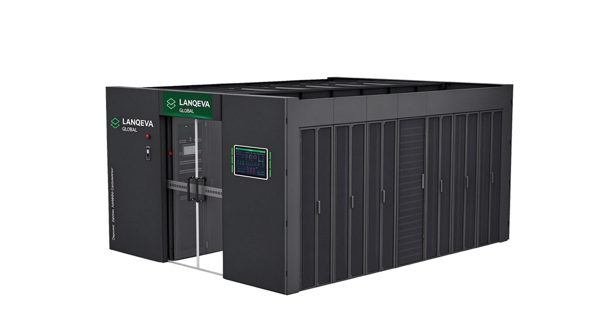
Power problems rarely announce themselves. In a data center, seconds of unstable utility power can take servers offline. Picking the right UPS (Uninterruptible Power Supply) matters more than a kW figure on a spec sheet.
The aim is not the biggest unit, but one covering today’s real load, holding equipment until generators start, and leaving room to grow.
Why Getting the UPS Size Right Matters
Besides blackouts, a UPS damps sags, surges, and line disturbances that wear out sensitive IT gear.
Wrong capacity cuts both ways: undersized units trip at peak load; oversized ones waste budget and efficiency.
A well-sized UPS should:
- Cover actual connected load, not just nameplate maximums.
- Hold the load long enough for generator pickup or safe shutdown.
- Absorb temporary load spikes before dropping offline.
- Leave headroom for planned rack additions.
- Stay efficient across its operating range.
The goal is a system that matches how the facility actually runs.
Step 1: Measure the Actual IT Load
Start with the gear the UPS must protect, not brochures. Label wattage is a rough pass; real draw differs.
Build a Critical-Equipment Inventory
Walk the room and list every device that cannot tolerate an outage.
- Rack-mounted servers and blade enclosures
- Network switches, routers, and firewalls
- Storage arrays and SAN/NAS systems
- Security appliances and monitoring gear
- Other essential IT infrastructure
Leave out lighting, office outlets, and unrelated plant loads on separate feeders. Track cooling separately if it needs backup.
Use Real Measured Consumption
Nameplate ratings are a ceiling, not a typical point; summing maximums inflates the UPS requirement.
Where available, pull actual draw from rack PDUs; the sample below shows the total.
| Equipment | Quantity | Power per Unit | Total Load |
| Servers | 20 | 500 W | 10,000 W |
| Network switches | 10 | 150 W | 1,500 W |
| Storage systems | 5 | 600 W | 3,000 W |
| Security equipment | 5 | 100 W | 500 W |
| Total | 15,000 W |
This load lands near 15 kW, a baseline that must still cover peaks and growth.
Step 2: Convert Load into Required UPS Capacity
Once the load is known, translate it to vendor rating. kW and kVA are the two units people mix up most.
- kW (real power): what the equipment actually draws.
- kVA (apparent power): what the UPS must be able to supply.
- Power factor (PF): the relationship between real and apparent power.
Required kVA = Load in kW / Power Factor
A Quick Capacity Example
Take a 15 kW connected load with an output power factor of 0.9.
15 / 0.9 = 16.67 kVA, so the unit must deliver at least 15 kW and 16.67 kVA.
That is the minimum, not the figure to buy. Before choosing, weigh:
- Future growth: servers or storage already on the roadmap.
- Peak demand: load spikes during busy periods.
- Operating margin: spare capacity so the UPS never runs flat out.
- Compatibility: output ratings that fit the connected equipment.
A 20-30% allowance above current load suits many projects; size it to the plan. 20 kVA is not 20 kW.
Step 3: Plan Battery Runtime
Capacity and runtime are separate: how much power the UPS feeds, and for how long.
With standby generators, the battery bridges the gap to start-up and buys shutdown time.
Typical Planning Ranges
No runtime number fits every facility; the ranges below are rough planning placeholders.
| Application | Typical Planning Range |
| Small server rooms | 5-15 minutes |
| Small and medium data centers | 10-30 minutes |
| Enterprise data centers | 10-30 minutes |
| Facilities without standby generators | Extended backup or shutdown requirements |
The right number depends on generator start time, load profile, and shutdown procedure.
What Changes Battery Runtime
- Connected load: the heavier the draw, the shorter the runtime.
- Battery capacity: the stored energy available to deliver.
- Battery age: capacity fades as the batteries cycle and age.
- Temperature: heat speeds degradation and weakens output.
- Discharge rate: usable capacity shifts with drain speed.
Ah ratings alone mislead; they do not state runtime directly. Ask runtime curves for the exact model and bank.
Step 4: Choose a Redundancy Configuration
Total capacity alone is not enough; plan what happens when a module fails or needs service.
N Configuration
N supplies only required capacity: a 100 kW load gets a 100 kW system.
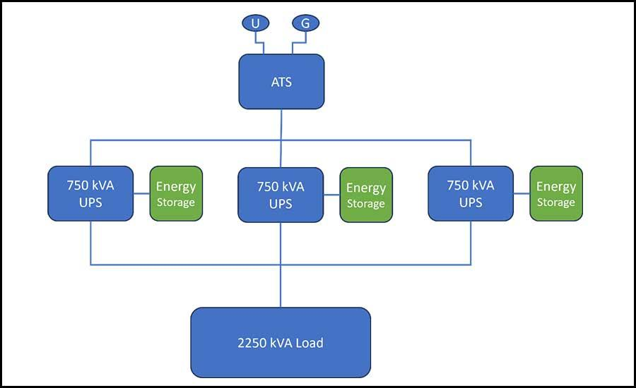
Figure 1: Parallel N arrangement feeding a common critical load bus
Cheapest and simplest, but no spare carries the load if it fails; it suits non-critical rooms.
N+1 Configuration
N+1 adds one module beyond the minimum; with three carrying load, a fourth sits in reserve.
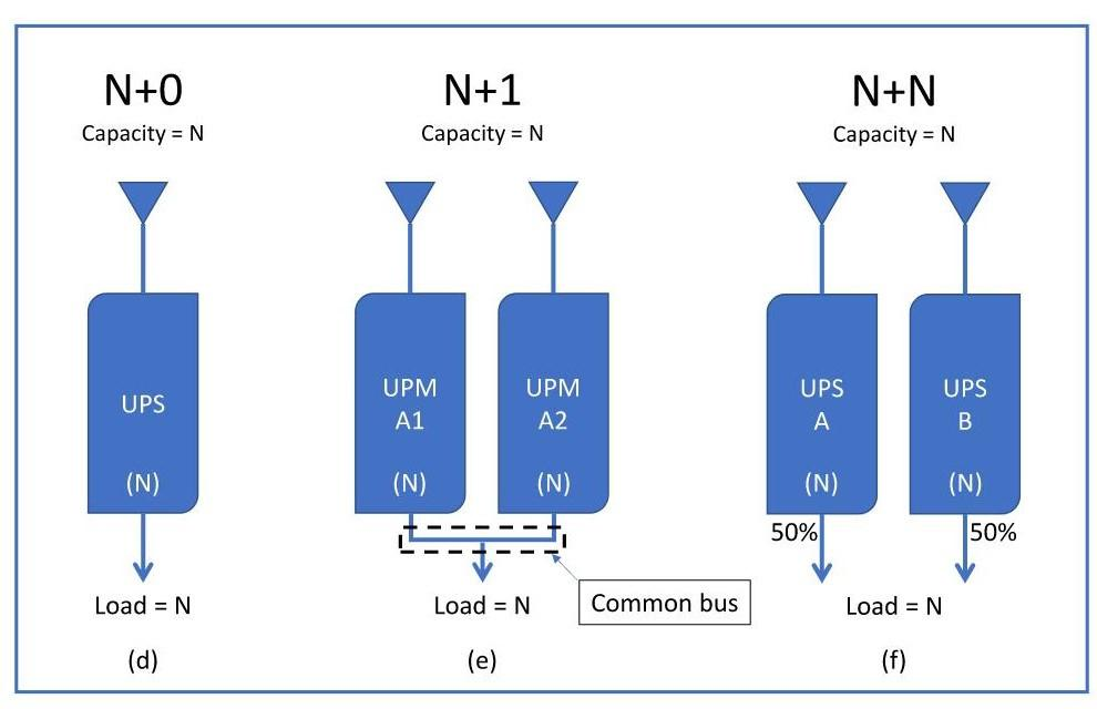
Figure 2: N+0, N+1 and N+N redundancy arrangements compared
It balances reliability against cost and fits these cases:
- Protection against a single module failure.
- Maintenance can run without interrupting the protected load.
- Expected load growth over the next few years.
After one module drops out, the rest must cover the full design load; that is true N+1.
2N Configuration
2N uses two independent paths, each carrying the full critical load alone.
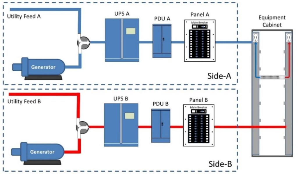
Figure 3: 2N dual-path architecture with Side A and Side B feeds
If one path fails, the other keeps equipment running with dual-feed distribution. The cost is doubled capacity, batteries, switchgear, and space.
Even 2N leaves weak points; breakers and transfer paths still need a review.
Step 5: Select the Right UPS Topology
Topology sets output quality; online double-conversion suits critical rooms best.
Online Double-Conversion UPS
Online double-conversion converts AC to DC, then back to regulated AC via the inverter.
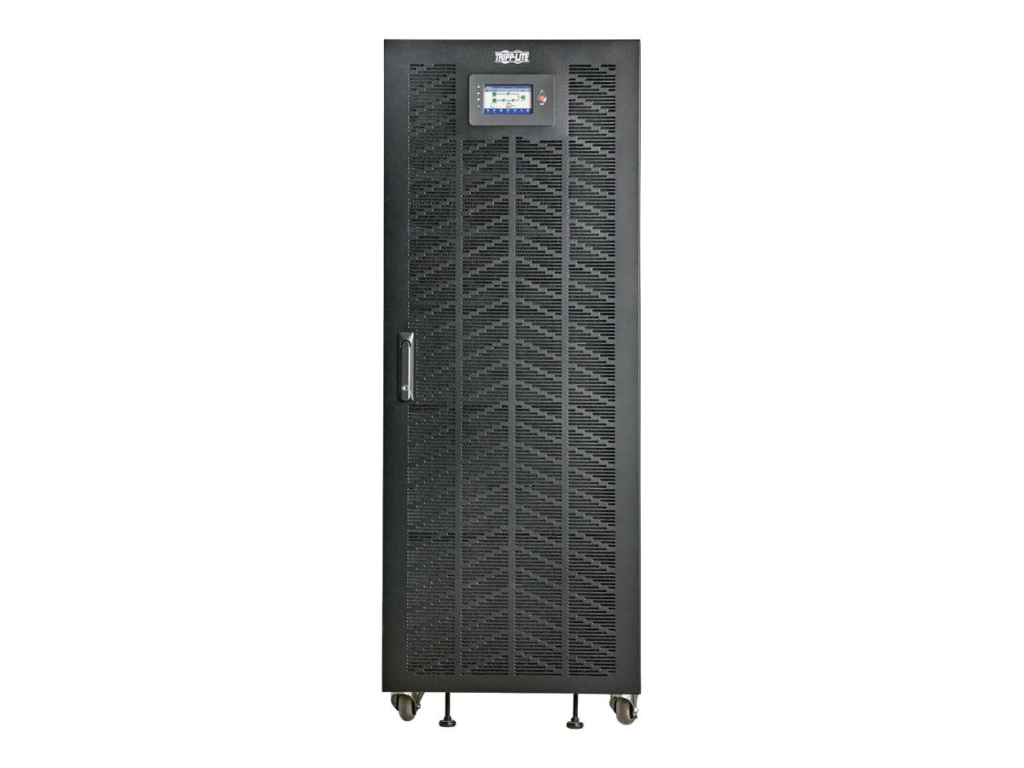
Figure 4: Floor-standing online double-conversion UPS cabinet
The inverter carries load continuously, so battery switching has no gap. Strengths:
- Rides through input sags and surges without a hitch.
- Holds output voltage and frequency steady under changing load.
- No interruption when utility power switches to battery.
- A natural fit for sensitive servers and storage.
Line-Interactive UPS
Line-interactive units use voltage regulation to smooth mild fluctuations before touching the battery.
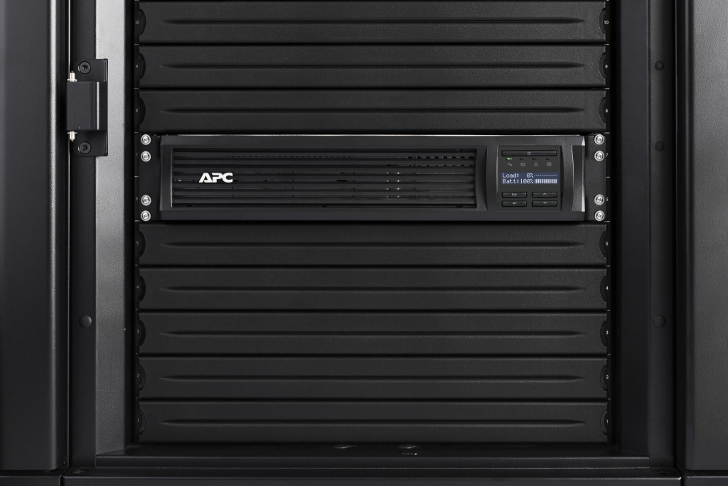
Figure 5: Rack-mounted UPS installed inside a server cabinet
Lower cost and light-load efficiency suit small closets; large rooms prefer double-conversion.
Step 6: Plan for Growth and Efficiency
A UPS chosen today may serve a larger IT estate in three years; plan growth.
A Modular UPS for Growing Data Centers
Modular systems add power modules as demand rises, avoiding a large upfront purchase.
- Capacity tracks actual growth rather than a forecast.
- Expand by adding modules, not replacing the frame.
- A smaller upfront investment.
- Module-level maintenance and swaps.
Before choosing, confirm the expansion limit and whether future modules are compatible.
Compare Efficiency at Real Loads
Full-load efficiency figures can mislead; real performance often differs at 30-50% utilization.
Ask for efficiency curves across load levels, then weigh the running costs below:
- Steady-state power draw under normal load.
- Heat released and the cooling load it adds.
- Battery charging losses.
- Service visits and spare-part costs.
- Expected battery replacement interval.
Over ten years, these items materially affect total cost of ownership.
Step 7: Check Installation, Batteries and Monitoring
A correctly sized UPS still fails if the room cannot support it. Check these before ordering.
Physical space:
- Cabinet footprint, weight, and floor loading.
- Clear access for service and filter swaps.
- Ventilation and ambient cooling headroom.
Battery chemistry:
- VRLA lead-acid: cheaper up front, proven, heat-sensitive.
- Lithium-ion: longer life, higher density, higher price.
Monitoring:
- Live load and power-quality readings.
- Battery health and remaining runtime estimates.
- SNMP integration and alarm alerts.
- Event history logs for troubleshooting.
Worked Example: Sizing a 30 kW Data Center
Worked case: 30 kW critical load, 25% growth, 0.9 power factor, 15-minute runtime, N+1.
| Parameter | Value |
| Current IT load | 30 kW |
| Planned growth allowance | 25% |
| UPS output power factor | 0.9 |
| Required battery runtime | 15 minutes |
| Redundancy | N+1 |
Step 1 – Apply growth: 30 x 1.25 = 37.5 kW.
Step 2 – Apparent power: 37.5 / 0.9 = 41.67 kVA; the system must cover at least 37.5 kW and 41.67 kVA.
Step 3 – Lay out N+1 modules so 37.5 kW survives one outage. Step 4 – Size batteries for 15 minutes from discharge curves.
This sets the selection direction; a final design still verifies ratings and fault protection.
Pre-Purchase Checklist
It is easy to over-weight headline kVA and price; run through this checklist:
- Does the rated output cover the required kW and kVA?
- Is there headroom reserved for future expansion?
- Will the battery bank meet the target runtime?
- Is the redundancy level (N, N+1, 2N) a good fit?
- Is online double-conversion actually required here?
- Are battery replacement and service costs reasonable?
- Has efficiency been checked at the real operating load?
- Is remote monitoring and SNMP support included?
- Can the supplier handle delivery, install, and commissioning?
- Are spare parts and local support easy to reach?
Ask for datasheets, runtime curves, and references from similar installations.
Final Thoughts
Sizing a UPS for a data center means matching protection to real conditions. Start with an honest load measurement, then work through capacity, runtime, redundancy, topology, growth.
Do not ignore installation and maintenance; they shape lifetime cost as much as price. Aim for a system serving today’s load with room to grow.
Data Center Infrastructure | LANQEVA Global